Wednesday 19th April 2023
Just Peter and Bill today with Patrick arriving at lunch time for perhaps this last survey session. Bill had found a study on rood turrets which had caused peter some concern. Their construction (given the type in Wigan i.e. octagonal in section) suggest a much later date than Peter had assumed. Their red (Triassic) sandstone blocks are very similar to the the bocks used in the construction of the tower, so Peter had assumed they were of the same date (i.e.13th century). A quick internal inspection confirmed they are very similar (although the blocks are actually slightly small than the tower’s). There is also an early B&W photo of the tower taken before the recladding in the 1922 which seems to show that the buttresses were made of the same stone as the tower. 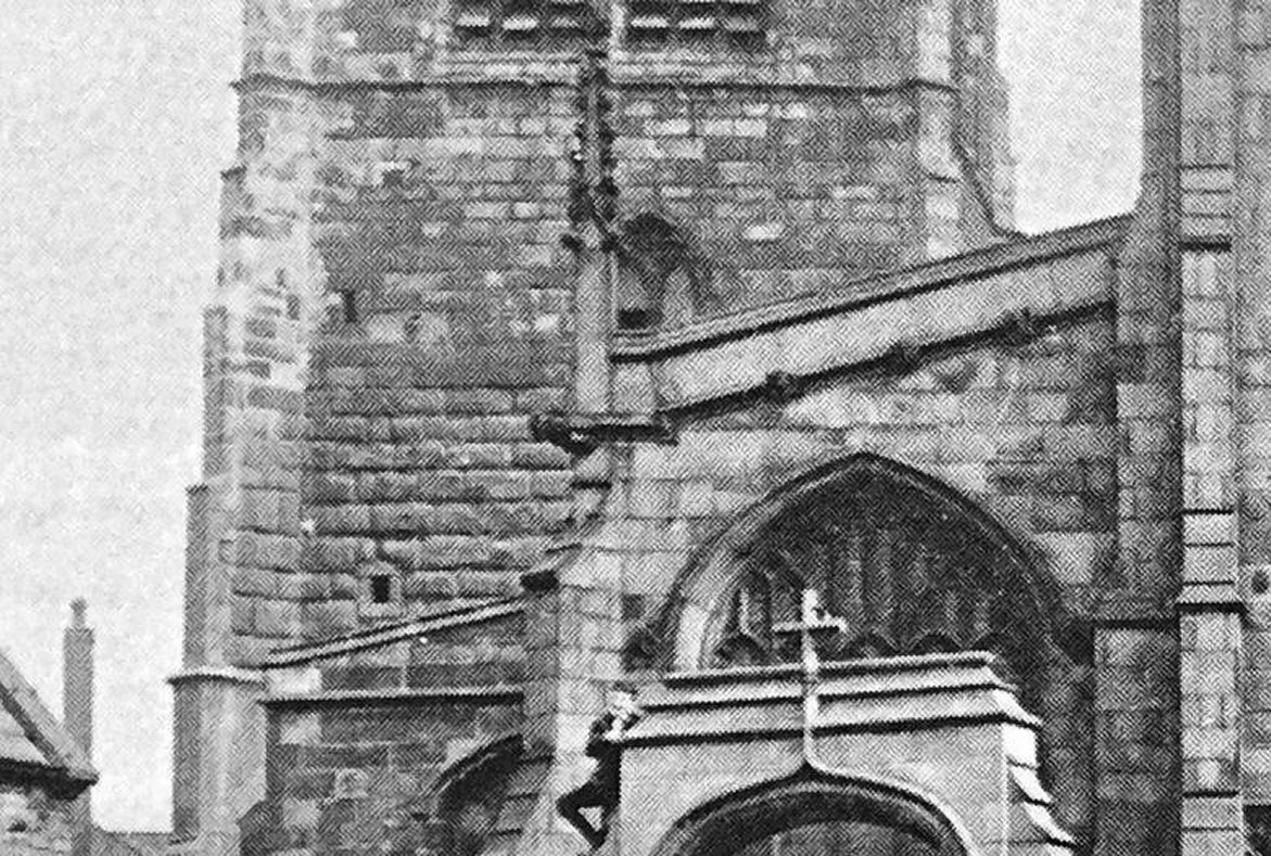 Again Peter had assumed they were a later addition as that style of buttress (i.e. angled at 45°) only came after the 14th century (walls as thick as at Wigan would not have needed them so their addition is purely decorative). Does this mean we have the date of the tower’s construction wrong, but this doesn’t seem likely given the style of the large entry arch and the window in the west wall, or did the builders returned to using red sandstone for these later constructions.
Our work today concentrated on again on the upper parts of the tower and the spiral staircase. While Peter was giving Patrick a tour of the upper parts, Bill measured the height from entry floor to top step in to the bell ringer’s chamber as 870cm. With 39 steps, this give an average height of each step at around 22cm and with two and a quarter revolutions gives an average of around 21° for each step. Height into the belfry was also measured from the door step to the top step as 560cm and more dims were taken in the clock mechanism room.
While in the clock mechanism room, an opportunity presented itself to view the movement in operation. It wasn’t working when we first visited as the guy responsible for maintaining had retired some four year previous. However experts from Cheshire had been found who knew how to get it working again. It was fascinating to watch the clock’s working mechanism as it struck the hour bell and quarterly hour chimes (trip switches triggered from cams and timing discs).  Bill had previously been in contact with a descendent of the Potts company who had built the clock. Although the plaque said 1968, in fact it was original constructed 1897 and installed in St Andrew’s Church, Bradford. When that church was demolished in 1967, the movement was taken back to the works in Leeds for reconditioning and electrification. It was then installed into the tower replacing the previous one there. Even that wasn’t the original clock as the huge steel beams the clock was mounted on suggest a Victorian date. Most likely therefore, the previous clock was located there when the tower was extended in the late 19th century. It is presumed the original clock was located above the belfry at the same level as where the clock faces are shown located in pre-1850’s drawings i.e. between the two arches of the belfry windows. This is because the wooden casement still exists in the belfry for the clock weights. The holes for the drive shaft to the clock faces can still be seen, however it isn’t clear how the clock would have been mounted.
  Before finishing for the day Patrick was keen to have another look at the (assumed) guarderobe to see if there was a hole actually under the apparent seat (if not, the theory of a Medieval toilet could be immediately dismissed). Thinking on the same lines Bill had fortunately brought a bucket and trowel. After a few minutes of scraping it became obvious that there was a recess but it was blocked with mortar. Hitting the mortar revealed it to be hollow and in one corner, were the mortar had broke away, there was a hole.
 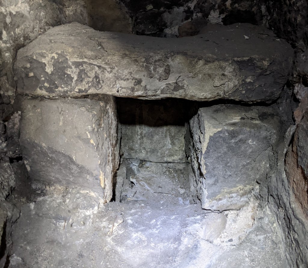 This at least did show that there does seem to be a chute under the seat, the possibility of this being a guarderobe therefore still persists (one theory is though that it could have originated as a drain if this was the level of the original roof).
Wednesday 22nd March 2023
Down to three this week – Peter, Bill and Andy, but despite this we seem to get quit a lot done. First task was to see if we could improve on the dimensions for the outside of the tower. Last month we had used the function on laser measure device which can work out heights using Pythagoras. This had been partly successful but there was a mismatch between the height of the lower cladding and the bell ringer’s chamber windows which Bill was keen to resolve (the attempt to measure the Walmesley Chapel gable using the device had given us less confidence in its efficacy). This time Bill had brought a 50m tape with a weigh attached to the end with the plan of dangling it down from the parapet. The idea was that Andy, on the ground using a walkie-talkie, would say when the bottom of the tape reached the significant features on the tower so that Bill could record the distance from the top of the parapet. The plan was sound but unfortunately we had pick the wrong day as the gusting wind was blowing the tape (even with the large weight) around the tower buttress. We decided to wait until the wind died down or perhaps try again on a calmer day.
In the calmness of the bell ringer’s chamber Bill took the opportunity to take more readings of the panelling before moving up for another look at the clock mechanism room. Here the huge girders supporting the belfry are exposed and could easily be measured. The steps leading up to the belfry were also recorded. The spiral staircase ends at this point and it is obvious that the entrance into clock mechanism room is a modification, the original route being blocked up.

Top of Spiral Staircase
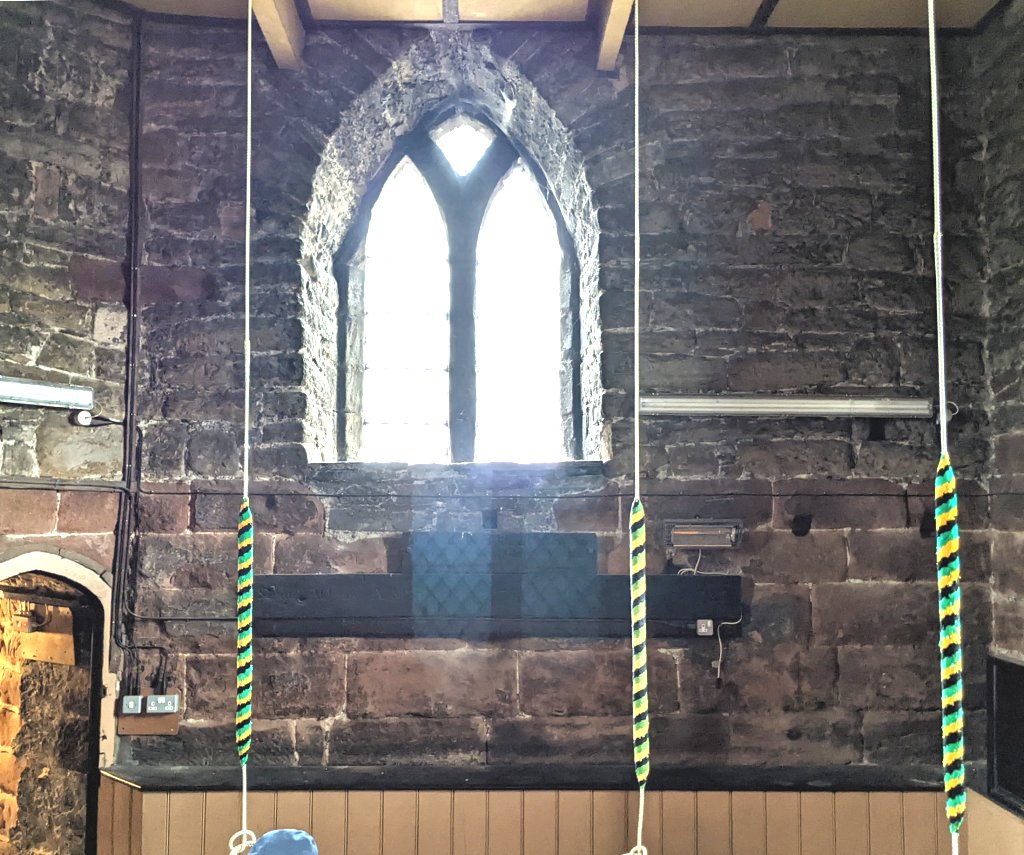
After lunch Bill continued to record more details of the belfry room. As mentioned before the bottom sections of the belfry windows have been bricked up and with all the modifications over the years it was difficult to see the windows’ bottom ledge. However a hole through the brick gave access to see where this was. In the top corners of the belfry room are corbels which are helping to support the clock face room floor. It suggests that this was perhaps the position of the tower’s roof prior to the 19th century extension.

Belfry
To get to the clock face room (where the bevel gear is located) another smaller spiral staircase is located in the NE corner of the tower in the belfry room. Its starting point is lower than the current belfry floor which suggests an earlier floor level. Besides the gearing, the clock face room contains massive wooden beams on two levels. These not only support the roof but also the large flag pole located in the centre.
With as many measurements taken as thought necessary, there was time for another go at taking measurements on the outside. The wind although still gusting was not as severe and by dangling the tape down the north was, it was sheltered by the NW buttress. This time we managed some level of success.
Thursday 16th March 2023
Only four again today – Peter, Bill, Bob and Andy. Most of the work today was carried out in the bell ringer’s chamber and above. First priority was to get a dimension from the panelling to the wall behind it (from previous visit we had established the overall dims but not the location). This having been done we then tried to get a dimension for the height of the step behind the panelling (this proved almost impossible as the tongue and grove of the panelling produced few gaps). Eventually we had to settle for the height of the wall step revealed in the cupboard in the SW corner. Here the wall step has been cut away to allow for the weights for the original clock mechanism to dangle (and also it turns out the present mechanism).
While Bill was rechecking the dims of the windows, Bob and Andy were tasked with producing a detailed drawing of the north wall’s red sandstone blocks (this side being the most visible and least eroded – east wall erosion is up to 20cm in places).
Bell Ringers Chamber north wall
Bill also wanted to check the width of the room east-west to see if the ‘angling’ of the west wall revealed on the ground floor, continued in the bell ringer’s chamber. Measurements indicated a slight difference (5cm) but this was in the wrong direction i.e. the larger dim was on the north side.
Next task was to check the floor level of the bell ringer’s chamber as we had had varying results from our previous attempts (embarrassingly last time out our laser light, shining through the bell rope hole, had been spotted by the curate during his service ). Bill had brought a small plumb bob this time which fitted through the hole which gave us a pretty accurate assessment of the floor’s height. We were also able to do the same for the clock mechanism room.
Before move up to the clock mechanism room, Bill and Andy took dims of the spiral staircase steps leading up to the blocked door in the bell ringer’s chamber. Bill counted 15 steps down to another blocked doorway which presumably gave access to an earlier room between the ground floor and the bell ringer’s chamber (whose floor would have originally been at the higher level indicated by the wall step behind the panelling). A further block door can be seen further down which Peter suggests gave access to a galley on in the ground floor room).
In the clock mechanism room, Bill was able to get dims for the large step in the wall which supports the steelwork for the bells in the belfry room above. The height of this step varies east-west and north-south, the north-south seemingly adjusted to accommodate the huge steel girders spanning across the tower. On the south side, there are further cut-outs in the step whose purpose is not known. The clock mechanism itself (which is still in working order) is supported on steel beams inset into the tower wall. A plate on it says the makers were Potts & Sons, Leeds with a 1968 date. This however we suspect refers to its upgrading to being electrically powered as its structure strongly suggests a much earlier manufacture (even 19th century).  The basic drive still relies on a huge weigh dangling down the original weight shaft in the SE corner of the tower, but a geared motor, driving a chain, automatically winds the cable back up on a drum when the weight reaches the bottom (a square drive shaft suggests this was originally done by hand). Two more similar motors drive cams which work wires attached to bell cranks to operate the hammers to chime the quarter hour and hourly bells (this was slightly alarming when not prepared for when visiting the belfry). A single driveshaft travels up through the floor of the belfry and up through the bells and floor above. In the room above there is a bevel gear arrangement which distribute driveshafts to the four clock faces.
 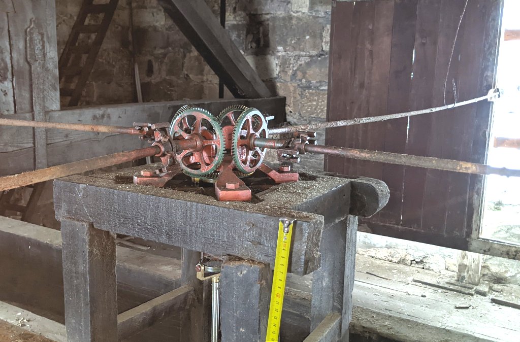 Whilst in the belfry Bill was able to get some general dims for the belfry windows. This was difficult as it was apparent that there had been a lot of work carried out on them in recent years. This included replacing the stone louvres which had become loose and presented a danger to passers by. More significantly the lower sections of the windows has been bricked up on the inside rendering the original base difficult to detect. Bill did however manage to get a rough idea of the window’s height.
Our final task of the day was to see if we could get a dimension for the height of the Walmesley Chapel outside. Our height measuring stick not being long enough, we resorted to using our laser measuring devise using its ‘Pythagoras’ function which seemed to work well last time out. Despite several attempts, the result was not convincing however and in the end we resorted to taking a photo of the gable end with our surveying staff along side.  This, together a monopod photo of the roof relative to the tower wall, hopefully will give us the dims we’re after.
  Note the buttress on the south west corner cutting away to allow for the roof of the north isle of the church. This is proof that the buttresses are purely decretive.
Wednesday 15th February 2023
Only four of us today – Peter, Bill, Bob and first-time visitor Steve Taylor. Bill needed to do more checks around the west wall of the Tower to try to understand why some dimensions weren’t matching up. On the Chapel side of the west wall there was a horizontal step behind the Chapel’s altar 2.25m high and 28cm thick, and a vertical step on the inside of the south wall of the chapel 83cm deep and 11cm thick. Both steps were adding to the difficulties in getting accurate measurements (not to mention the alarm system protecting the 15th century carved wooden altarpiece, which came from the rector’s private chapel at Wigan Hall – now installed above the Chapels altar).

Walmesley Chapel east wall
Our work was halted by the usual Wednesday service at 12.30 – time for lunch. Bill was wanting to do some measuring outside and was worried about predicted rain later in the afternoon. He therefore decided to do the measuring straight away, helped by Bob. He was keen to try out a function on the laser measurer which gives you heights of structures. If he could get it to work it would prove very useful for measuring the height of the various external components of the Tower. The technique involved mounting the laser on a tripod and taking two readings, first from the feature to be measured and the second from a horizontal point on the wall at known height (it’s simple Pythagoras but the laser works it out for you). The system seemed to work fine and a good number of readings were taken including the steps in the Tower’s buttress and the positions of two stringer courses running around the tower as well as the height of the lower cladding.  The limit of this technique was reached however when the beam became difficult to see beyond the second stringer course (a suggestion was to return when the daylight is going so that the beam would become more visible).
After lunch we ventured into the Bell Ringer’s Chamber to check on the dimensions obtained on the previous visit. Although we had the internal size of the chamber, it’s relationship with the ground floor room was could not be obtained (the chamber being about half a metre bigger). Steve noticed a pain of glass missing in on of the widows so we attempted to get a measurement of the wall thickness through it (this would at least give us a value in one direction). However looking behind the wood panelling that surrounds the lower half of the Chamber, we noticed that the stone wall steps out. It seem logical that this step represents the continuation of the inner wall from the ground floor room. If we could measure this step relative to the wall of the Chamber we would have the information we need. Using the think blade of a trowel (which Steve had fortunately brought along) we were able to get a measurement from the step to the outer surface of the wood panelling. Unfortunately we didn’t get the crucial dimension from the panelling to the wall of the Chamber (something for next time).
The other dimension Bill was keen to check was the depth of the floor of the chamber. His previous dimensions had shown this to be almost one metre thick which didn’t seem correct. The dimensions had been obtained by shining the laser through the hole for the bell ringer’s ropes. We looked therefore at an alternative method which involved dropping a weighted wire through one of the holes until it appeared in the ground floor room. The is confirmed the thickness was large at just under 90cm.
Thursday 2nd February 2023
Joining Peter this week were Bill, Chris, Eric and Bob. Chris was keen to have another go with the LiDAR function on his new iPhone, so straight away go going with a visit to the upper levels of the Tower. With the dimensions we got from measuring the inner and outer walls of the Walmesley Chapel on our last visit, Bill has been able to get an accurate size of the Tower in the north-south direction (showing it to be less then he originally estimated but still revealing the north wall to be almost 2m thick). He now wanted more measurements from the inner wall of the Chapel to enable him confirm the thickness of the west wall.
Peter pointed out that the outer face of west Tower wall (i.e. the east wall of the Chapel behind its altar) was not square with the rest of the Church. This could be seen in the floor tiles which had been lain square with the Church itself but were showing as much as a full tile difference across the width of the Chapel. The outer wall of the Chapel was showing only a third of a till out over its full length which was suggesting the Tower itself was not square with the Church. This needed to be checked out.
Before arriving on site Bill had been learning more about the laser measuring device they had been using (a Leica Disto machine) and had realised there were number of functions available that would prove very useful in this survey work. One in particular would now come into its own i.e. its ability to measure the corner angles. Using this function Bill was able to measure the angle between the east Chapel wall (i.e. outer face of west Tower wall) and the outer Chapel wall which came to 87°. To check the alignment of the Tower to the Church, Bill laid the laser flat on the wall inside the Church (i.e. on the outside wall of the Chapel) shining the beam across the face of the Tower entrance. Contrary to expectations, there appeared to be no misalignment between the Church and the Tower. Bill also measure the angle between the inner face of the south Tower wall and the inner face of the east Tower wall. This also revealed little if any out of squareness. This was suggesting that only the west wall of the Tower was out of alignment.
Peter pointed out that the width east-west across the inner faces of the Tower did vary – by as much as 10cm from north to south (the north being the shortest). This seemed to confirm that the west wall of the Tower alone was at a slight angle rather than the whole of the Tower (when Bill drew it up later, the amount of misalignment on the inside of the west wall did not fully match the misalignment on the outside of it, which was much greater – more investigations needed).
Whilst on the ground floor Bill took more measurements using the laser of the windows just to enhance and confirm our previous ones. He and Bob also recheck the position of the spiral staircase and got an an estimate for the height of the blocked up doorway leading from the staircase into the Tower (see below). 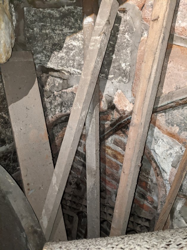 After lunch we concentrated on the bell ringer’s chamber and another function of the laser came in handy. This was the maximum and minimum function – when in use the beam is constantly measuring. When the beam is released, the maximum and minimum values are displayed. The proved useful when trying to obtain the distance from the floor of the chamber to the floor of the ground floor by shining the beam through one of the small holes used for the bell ringer’s ropes (two of which went down to the ground floor). It was impossible to see when the beam hit the floor but we knew it had when we saw the large value on the machine. We were grateful to get this dimension as, at the time, we couldn’t think of any other way of obtaining it.
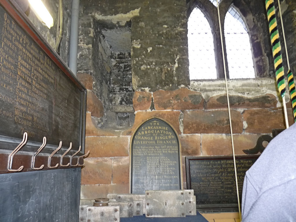
Whist in the chamber we took as many dimensions as possible which we thought relevant to our survey. These included the windows, three in all (no window in the south wall), the height of the changeover from large red sandstone blocks to the smaller grey sandstone blocks and the height of the original floor level (demonstrated by the blocked up original entrance to the chamber – see below).

Blocked doorway showing upper left behind the presentation boards
Of particular interest was the alcove which, to all intents and purposes, is a guarderobe (i.e. Medieval toilet normally only found in castles).
Guarderobe showing top left
Closer inspection of it did not prove it to be otherwise – with, what looks like the original seat still in place.  What Peter was being surprised about was the amount of erosion suffered by the red sandstone blocks (which he referred to as Triassic sandstone) in places up to 15 to 20cm deep. This was suggesting the Tower had been open to the the elements for some while, at some point in its life. If it was originally a defensive structure then there would have been a parapet but this would have a been on top of the walls which would have allowed a roof to sealing the inside of the Tower.
Another possibility however, is John Smalley’s theory about the bio-degradation of the sandstone. This was something he is proposing to explain the disappearance of all the stone excavated from our ring ditch in Aspull. His suggestion is that when exposed to the damp, microorganisms attack the stone surface causing it to disintegrate. In effect it only needs air and moister for it to erode, rather than full exposure to the wind and rain (although this has yet to proved conclusively at our site in Aspull). There are however plenty signs of biological activity on the original surfaces (lichen or algae) particularly in the gaurderobe (indicated by the patches of black rather than being soot from burning).
Wednesday 18th January 2023
Another good turnout for this our second visit – joining Peter this time were Bill, Chris, Andy, Eric, Bob, John Needle and newcomer Mike Keulamans with Mark Tildesley joining just before lunch.
First job was to revisit some of the previously measured dimensions to confirm and clarify the values obtained. Bill had realised a crucial dimension was the thickness of the Walmesley Chapel walls as this would give us the overall size of the tower in the north-south direction (east-west had been obtained due to the new door through to the vestry). Obtaining the width of the inside wall the of the Walmesley Chapel wasn’t a problem, as was the width of the Chapel itself (once the alarm system protecting the precious altar screen had been switched off). However the outside wall was a different matter requiring us to chase dimensions through the outside door of Chapel..
Since our last visit, Chris has indulged himself with a new iPhone which apparently has LiDAR technology on it. He was therefore keen to test it out and therefore spent sometime therefore wondering from floor to floor scanning the rooms we have access to (his initial results are quite crude but very promising).
After the break for lunch our numbers were reduced as (Chris, Mike and eventually Eric leaving early). Bill was keen to get dimensions of the ground floor windows (particularly the blind one on the west wall). To do this he had to climb on the cupboards using steps Peter found in the room next to the chancel.  This proved fruitful as, not only did he get the dimensions he need, he also got to see through a broken glass pane to view the makeup of the blocking wall. This revealed it to be made of large ceramic bricks. Peter concluded, therefore, that it most have been re-blocked when the Walmesley Chapel had a major refurbishment in 1955, rather than being an early construction (in fact pre 1955 photo on the Wigan Parish Church website shows the window unblocked in the Walmesley Chapel).
Regarding the Walmesley Chapel (also known as the Gerard Chapel) we had a discussion about when it was constructed. The architecture of the current building, particularly the windows, strongly suggests Tudor. However the archways connecting it to the rest of the Church look Medieval (in fact similar to the tower archway) suggesting an earlier version must have existed. Surely though, whatever this earlier construction consisted of, it could not have been contemporary with the tower otherwise there would be no point of the window in its west wall.

Walmesley Chapel
Wednesday 11th January 2023
This is our first survey visit and was well attended – joining Peter Layland were six of us, Bill, Chris, Andy, Eric, Bob and John Needle. After a brief introduction for those hadn’t been before, we split our team in two, one to work inside and the other outside. Inside, Chris’ team were tasked with getting the major dimensions of the ground floor under the tower using a plan created by the architects prior to the church rebuild in the 1849 (see below). The tower is almost unaltered by the rebuild, just a small new door knocked through the east wall to access the new vestry which replaced the ‘Lumber Room’. The only other change at this level was the discovery of a bricked up window on the west wall of similar proportions to the large one on the north wall. It still has its original tracery which is similar in style to the large gothic arch entrance to the tower and smaller arches between the north isle and Walmsley Chapel (obviously neither the window nor the new door are shown on the pre-1849 plan).  Meanwhile our team on the outside set up the dumpy level so that heights inside and out could be matched. The back site was taken from the top stop of the entrance to the tower and the fore site was taken from the top step of the entrance to the Walmsley Chapel (various other intermediate levels were also taken). External dimensions of the tower were also taken.
Work on the inside was curtailed at 12.20 to allow for a mid-day service in the Church. This gave Peter a chance to give people who hadn’t seen it, a visit to the first floor bell ringers room. When they returned we broke for lunch in the adjacent amenity building.
After the break efforts were concentrated on the inside to extend the range of dimensions taken before lunch. To do this we had other tools besides tapes, including a laser range finder and a surveyors extendable staff. These dimensions will enable Bill to produce a detailed drawing and perhaps even a 3D model. Chris also took a series of photos to see if he could produce a 3D image that way.